
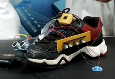
Blind Shoes project, Blind Shoes project for kids is a smart device designed to help people who are both deaf and blind move around safely and communicate during emergencies. It uses a Raspberry Pi, a camera, an ultrasonic sensor, a GPS module, and four buttons to give real-time guidance and send emergency alerts.
Blind Shoes project focuses on creating an assistive device to aid individuals who are both deaf and blind. The device leverages various sensors and modules, integrated with a Raspberry Pi, to provide real-time navigation assistance and emergency communication. The system is designed to enhance the user’s independence and safety by offering haptic and auditory feedback based on the selected mode and sending emergency alerts when needed.
Components Required
- Raspberry Pi (with Internet connection)
- Camera Module
- Ultrasonic Sensor (HC-SR04)
- GPS Module
- Vibro Motors (2 units)
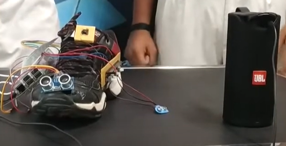
- Speaker
- Buttons (4 units)
- Resistors (4 units, 10kΩ each)
- Breadboard and Jumper Wires
- Power Supply
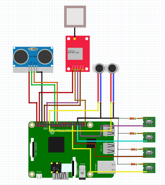
Circuit Connection
- Camera Module:
- Connect the camera module to the dedicated camera interface on the Raspberry Pi.
- Ultrasonic Sensor:
- VCC to 5V
- GND to GND
- Trig to GPIO pin 23
- Echo to GPIO pin 24
- GPS Module:
- VCC to 3.3V or 5V (depending on your module)
- GND to GND
- TX to GPIO pin 15 (UART RX)
- RX to GPIO pin 14 (UART TX)
- Vibro Motors:
- Connect the first motor to GPIO pin 17 and GND
- Connect the second motor to GPIO pin 18 and GND
- Speaker:
- Connect to an audio output pin (e.g., through a 3.5mm jack or USB sound card if your Pi doesn’t have an audio jack)
- Buttons:
- Button 1: Connect to GPIO pin 4 and GND (with a pull-down resistor)
- Button 2: Connect to GPIO pin 5 and GND (with a pull-down resistor)
- Button 3: Connect to GPIO pin 6 and GND (with a pull-down resistor)
- Button 4: Connect to GPIO pin 13 and GND (with a pull-down resistor)
Circuit diagram is given below:
Working
- Emergency Button (Button 1):
- When pressed, this button triggers an email containing the user’s live location (obtained from the GPS module) to a pre-configured email address. This is crucial for situations where the user needs immediate help.
- Mode Switch Button (Button 2):
- This button toggles between two modes:
- Deaf and Blind Mode: Uses vibro motors to signal directional guidance based on the input from the ultrasonic sensor. If an obstacle is detected on the right, the right motor vibrates, and similarly for the left.
- Blind Mode: Uses a speaker to provide audible instructions. The device speaks directions such as “move left” or “move right” based on the input from the ultrasonic sensor.
- This button toggles between two modes:
- Live Streaming Button (Button 3):
- When pressed, this button initiates live streaming through the camera module and sends an emergency email stating “I am in trouble” along with the streaming link to the designated email address.
- Help Button (Button 4):
- This button also initiates live streaming and sends an email with a specific request, such as “Help me to buy groceries,” along with the streaming link to the given email address.
Contact us at:
STEMROBO Technologies Private Limited
Toll Free: 1800-120-500-400
Email: sales@stemrobo.com
Website: www.stemrobo.com